Leased Lines
with a Dialup Modem
Floyd
Kling
Periodically I get asked if it is possible to use a
Dialup modem in a LL (Leased Line) application. The fast answer is, "Yes,
It's possible, but needs a bit of explanation.
First some basics about leased lines.
A leased line is just that.. a pair of wires you
may rent from your telco provider that are basically 2 wires that go from point
A to point B. They have no battery voltages, no dial tone, no call
progress signal nor anything like a conventional Dial Up network.
Look at a leased line as a pair of wires on your
bench... that's all... nothing more.. (there are also 4 wire leased lines,
but I'm not going to get into that right now.. you can email me if you have
questions on that)
The good 'ol DAA's
In the old days Dialup modems were made with Transformer DAA's
(Data Access Arrangement's)...with a series relay that performed the on hook/off
hook operation. Today, these style modems are phasing out in place of the
more modern (smaller and cheaper) 'electronic' DAA's.
The problem with LL on a Dialup modem
Today's modems that have the electronic DAA's require a "battery"
voltage to power the Telco side of the isolation barrier.... leased lines do not
have this battery voltage. Also, since leased lines are point to point,
they do not have dialing facilities or any of the call progress signaling (dial
tone, ring back, busy... etc). Leased Lines assume the modems are
connected (off hook) 100% of the time, and do not need to dial or answer.
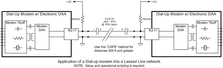
Hardware setup could be very simple.
For safety reasons, you might consider adding a 20uf/100V to
47uf100V in series with one of the two wires between the modems. Ideally
this should be a non-polarized cap, or you can simply make one out of two
identical caps, by putting them in series with each other with either the +
sides together or the - sides together... doesn't matter which way. You
have now made a Non-Polarized cap with the overall voltage of 2x the rating of
one and the overall capacitance of 1/2 the rating of one.
If you put the cap(s) in the line, then you must add a 1k
(1/4-1/2w) from either Tip or Ring to +12V. on each of the two modems. If
you have an extremely long long line between the modems, you may need two
Resistors plus the caps. Be sure to calculate the total resistance of the
wire and adjust accordingly. You should shoot for 10-20ma through the
modems and no more than about 30ma. You can see why you need to do this
for each modem... because you have put the cap in series which will block the
DC. You may ask why the cap... it is only for safety. In case
someone puts the modem into the standard Telco network and would then put that
12V/1k resistor to the telco system.
Make a "battery"
This is the trick that fools the Dialup modem into being
a LL. This can be a battery or a power supply - doesn't matter.
(I use the word "battery" because on dial up networks, the DC voltage
from the telco are actually real batteries.)
Here are two basic circuits. You can change the cap(s)
and resistor(s) configuration to fit your needs... i.e. for
shorter distances.. less than 1,000ft, it is possible to remove the caps
entirely and use only one resistor.
***It doesn't matter whether T or R goes to
+12V or gnd. Today's modems are
polarity IN-sensitive
If your distance is long, 1,000ft or
more you may need to use this method...
The capacitors are set 'back
to front' to make a quick "non-polarized"
cap. Values should be selected based
on the highest speed you wish to obtain.
They can actually be placed anywhere in the
loop. For speeds up to 33.6kbps, calculate
the total value to be greater than .20uf
(.47uf is fine). For speeds below
33.6kbps, .20uf should do it. (If your
expecting speeds above 33.6kbps (V.34),...
it's not going to happen... read
this.)
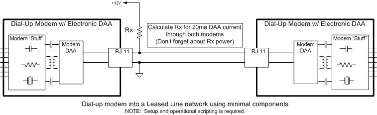
If your distance is short... less
than about 1,000ft, here is a simpler ONE
RESISTOR ONLY method with no caps.
Rx should be about 330ohms 1/4-1/2W.
This one resistor will supply current to
both modems DAA. Tolerance is not
important, value can actually be from about
220ohm to 600ohms. (Careful with the
resistor power dissipation.)
Setup and Operational Scripting
There are two modems in a LL connections... each must be defined
.. one as the 'originate' and the other as the 'answer'.. why?, full
duplex modems require this so they can negotiate a session and obtain a
connection speed.
It does not matter which modem is 'answer' and which is
'originate', it is only important that they are different.
Setup the 'Originate'
modem routine
To initiate the connection,
send the string: AT X0 D<cr> (BTW,
that's an X-Zero) spaces not necessary... (I
do the spaces for clarity) You should write
your routine to send this every 45 seconds(+)
until you see either a "CONNECT" Message, or
a "NO CARRIER Message.
If you see neither message
after 45 seconds... you should send a <cr>
to abort that attempt (actually any
character will work to force 'any key'
abort). After sending the <cr> you
will see a "NO CARRIER" message. At
that time, start the sequence again... AT X0
D<cr> and continue this indefinitely until
you receive a CONNECT message.
Setup the 'Answer' modem
routine
To initiate the connection,
send the string: ATA ...
no <cr> needed. Like the Originate
modem, write your routine to send this every
...say... 90(+) seconds.... until you
see a "No Carrier" or a "Connect" message.
Why 90 seconds?... you must have a different
time-out than the Originate modem so they
will not be in the same loop at the same
time and never find each other.
You may need to tweak the
connection routines... time cycling periods
may need to be optimized to ensure solid
performances. Ensure the timing cycle
on the Originate and Answer are different by
about 20 seconds or so.
I suggest you set both PC's (or Host
systems) DTE to 38400bps.. this will ensure
that regardless which speed the modems
connect, you will not slow down the
throughput... You can set them to 57600 but
the modems will not connect over 33600bps
because you have two analogue modems... read
this if you
want to know why.